
Submersible Deep-Well Pumps: Size by Flow and Head
Size a submersible deep-well pump using pumping water level, flow and pressure, then check casing fit, wiring, tank controls and filter backwash needs.
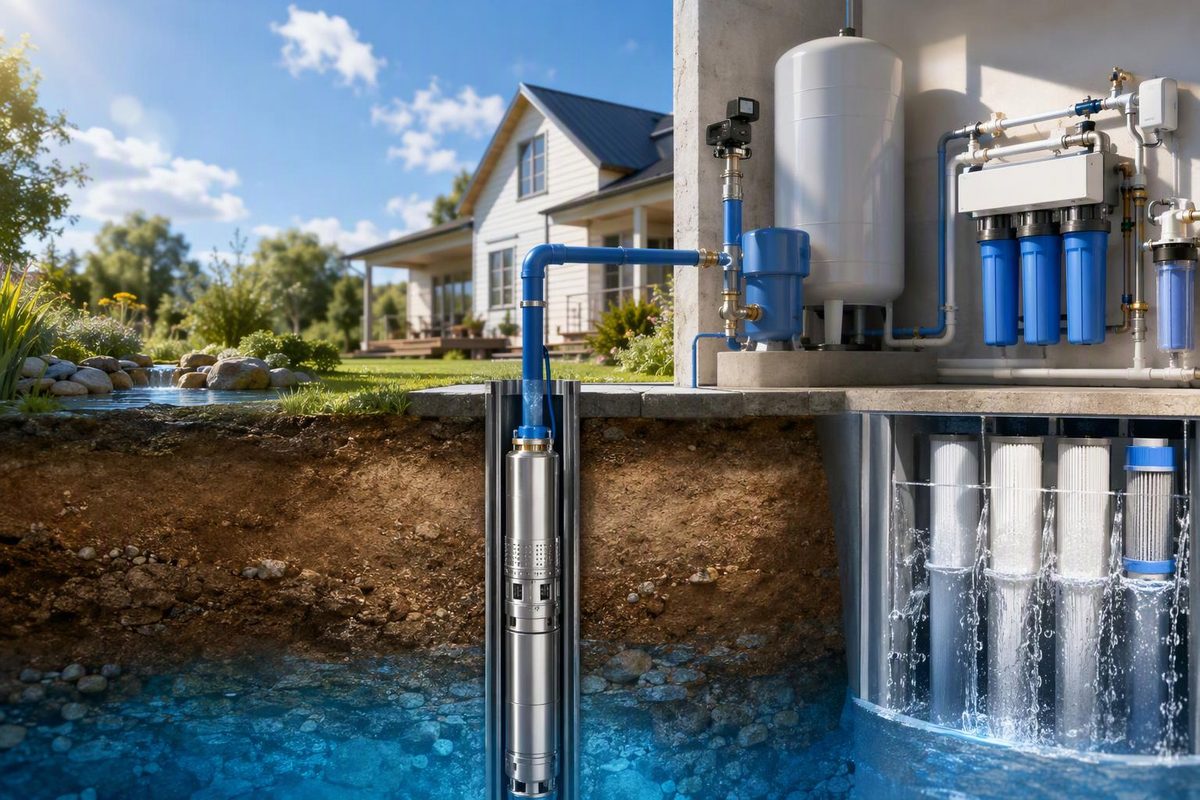
Choose a submersible deep-well pump by the flow it must deliver at your calculated total dynamic head—not by drilled well depth or horsepower alone. The pump operates underwater and pushes water through the drop pipe to the surface. Selection requires the pumping water level, required gallons per minute (GPM), delivery pressure, pipe losses, casing clearance and electrical supply. National Pump’s selection guide identifies these inputs.
The pump supplies water; it does not replace contaminant treatment. For a household with well-water filtration, include the treatment equipment’s pressure loss and any backwash demand in the design.
Start with the well record
These measurements answer different questions. Keep depths referenced to the same point, such as the top of the casing.
| Measurement | What it means | Why it matters |
|---|---|---|
| Drilled depth, ft | Distance to the bottom of the well | Establishes available installation space; it is not the pumping lift |
| Static water level, ft | Depth to water while the well is at rest | Provides the starting water level |
| Pumping water level, ft | Depth to water while pumping at a stated GPM | Determines lift under that tested operating condition |
| Pump setting, ft | Installed depth of the pump | Determines drop-pipe and cable length and intake position |
| Well yield, GPM | Rate the well can sustain without lowering water below the intake | Limits sustainable withdrawal |
| Casing inside diameter, in | Actual internal clearance | Determines whether the assembly can be installed and retrieved |
Ask for the driller’s log and a pumping test that records both flow and water level. Franklin’s pump installation manual directs installers to determine setting depth from static level and drawdown at the proposed pumping rate.
Set the household flow target from the uses that must operate together, then compare that demand with well yield. A bigger pump is not a remedy for inadequate yield. A low-yield system may need reduced peak use or an intermediate storage tank filled slowly from the well, with a separate pump supplying household pressure. A pressure tank alone provides limited usable storage. Penn State Extension explains these distinctions in Using Low-Yielding Wells.
Calculate head, then read the pump curve
For a typical well supplying a pressurized system:
TDH, ft = vertical lift from pumping water level to delivery point + pressure head + friction losses
For water, pressure head, ft ≈ pressure, psi × 2.31. National Pump documents the head calculation; Franklin’s residential pump catalog, conversion table gives the pressure conversion.
Use the pumping water level for vertical lift, but the full installed pipe length for friction—including the submerged drop pipe and the line to the delivery point. National Pump’s friction calculation uses loss per 100 ft multiplied by drop-pipe length, plus check-valve losses.
Example: 10 GPM at about 319 ft TDH
Suppose the design conditions are:
- Pumping water level: 150 ft below the wellhead at 10 GPM.
- Delivery point: 10 ft above the wellhead.
- Required pressure there: 60 psi, equivalent to 138.6 ft of head.
- Calculated pipe, valve and equipment losses along that path: 20 ft at 10 GPM.
The total is 150 + 10 + 138.6 + 20 = 318.6 ft TDH. These are illustrative inputs, not a recommendation for every 150-ft water level.
Find a model whose curve supplies the required 10 GPM at approximately 319 ft, within its published operating range. Then check operation across expected water levels and pressure settings. Franklin’s performance tables distinguish operating ranges, pumping lift and shut-off head, and explicitly exclude drop-pipe friction from the tabulated performance.
Do not read “maximum head” or “shut-off head” as a usable delivery rating: shut-off is the zero-flow endpoint. Nor does a nominal “10 GPM” label mean 10 GPM at every depth and pressure.
For an on/off pressure-tank system, have the installer verify that the pump can reach the pressure-switch cut-out setting at the expected low water level. Specify where pressure is required—at the tank or after treatment—so losses are neither omitted nor counted twice.
Check physical and electrical compatibility
Before ordering, verify:
- Actual assembly diameter: include the cable guard and necessary accessories, not just the nominal pump size. Franklin’s 3200 Series, for example, is called a 4-inch pump but lists a maximum diameter across the cable guard of 3.75 in. That dimension is model-specific. Franklin catalog
- Intake position and cooling: keep the intake submerged under expected drawdown. Confirm bottom clearance and whether water will flow over the motor; some installations require a flow-inducer sleeve. Franklin’s 2026 AIM manual identifies cooling requirements for large casings, top-feeding wells and pumps set in or below screens.
- Voltage, phase and starting controls: conventional single-phase two-wire motors have starting components inside the motor; three-wire motors require a compatible external control box. These names exclude the grounding conductor; both require grounding. Match the box to the motor’s horsepower and voltage. Franklin installation manual
- Cable, pipe and tank: cable sizing must account for the full electrical run. Drop pipe must suit installation depth and pressure. Size the pressure tank and controls to avoid excessive cycling; Franklin specifies at least a one-minute motor run to dissipate starting heat. 2026 AIM manual
Use a qualified well contractor and licensed electrician for installation rather than treating this selection checklist as wiring or pump-pulling instructions.
Include filtration before finalizing the pump
Give the installer the treatment system’s service-flow pressure drop and required backwash flow, pressure and duration. Backwash is a sustained demand, not merely a brief faucet-flow check. Culligan’s Iron-Cleer owner’s guide, for example, lists service pressure losses separately from minimum drain-flow requirements and backwash times. Use the manual for your exact filter, not those figures as universal targets.
For treatment selection, see the well-water whole-house system guide. After pump replacement or other well-system repairs, arrange drinking-water testing: EPA recommends immediate testing after repair or replacement of any part of a private well system. Restored flow and clear-looking water do not establish drinking-water safety.