
Commercial UV Water Treatment Systems: Sizing
Base selection on peak flow, minimum UVT and exact-model validation, with checks for pretreatment, controls, maintenance and lifecycle cost.
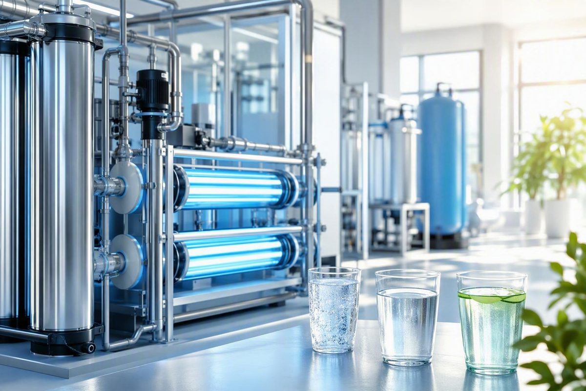
Commercial UV water treatment systems are often treated as a simple flow-rate purchase: determine the facility’s gallons per minute, select a unit with an equal or higher GPM label, and install it in the main line. That shortcut overlooks the conditions that determine whether a reactor can deliver its claimed treatment.
A defensible specification begins with four questions:
- What application and treatment objective apply?
- What is the maximum instantaneous flow?
- What is the lowest UV transmittance the reactor will encounter?
- Under which flow, dose, water-quality, lamp-aging, fouling, and hydraulic conditions has the exact model’s performance been documented?
The rest of the project—pretreatment, monitoring, shutoff logic, redundancy, downstream protection, maintenance, and service support—determines whether performance can be sustained after installation. Nominal GPM is useful, but only as one field in a larger operating envelope.
This is a procurement framework, not a substitute for an engineered design, regulatory determination, certification review, or manufacturer-approved commissioning procedure.
What commercial UV treatment does—and what it leaves untreated
A basic UV reactor contains one or more lamps separated from the water by watertight quartz sleeves. Water passes through the chamber around the sleeves and is exposed to UVC light, commonly described for this equipment at a wavelength of 254 nanometers. The light damages microbial genetic material, preventing susceptible organisms that receive an adequate dose from functioning or reproducing. VIQUA’s explanation of UV treatment describes dose as a function of UV intensity and the time water spends in the reactor.
In simplified terms:
UV dose ≈ UV intensity × exposure time
This relationship explains why flow matters. If reactor geometry and lamp output remain unchanged, faster flow normally shortens exposure time. Chamber design, lamp power, lamp count, and reactor hydraulics may compensate, but performance must be established for the exact reactor rather than inferred from lamp wattage or chamber volume.
Actual dose delivery is more complicated than the formula suggests. Water does not necessarily travel through a chamber along identical paths. Lamp placement, geometry, turbulence, intensity distribution, and hydraulic short-circuiting can cause different portions of the flow to receive different exposures. Model-specific validation is therefore more useful than a theoretical calculation based only on volume and lamp power.
UV is primarily a microbial-disinfection step. It is not a sediment filter, water softener, or general-purpose dissolved-contaminant removal system. Several of those conditions can also obstruct UV treatment or foul the lamp sleeve.
UV also leaves no lasting disinfectant residual. Once water exits the chamber, the reactor cannot protect it from contamination introduced by a storage tank, dead leg, damaged pipe, poorly maintained recirculation loop, or contaminated fixture. That limitation is especially important when considering Legionella, established biofilm, storage hygiene, and building-wide water-management risks.
UV may be one control point in a broader design, but it should not be represented as a complete standalone strategy for an entire storage and distribution system.
The application materially changes the specification:
- Potable point-of-entry treatment focuses on water supplied for drinking and ordinary building use.
- Food-and-beverage process water may have product-specific microbial and quality objectives.
- Healthcare and high-purity loops may require specialized microbial controls, recirculation design, monitoring, and downstream safeguards.
- Wastewater and reuse applications involve different water quality, UVT, hydraulics, targets, and validation frameworks.
- Pools and spas are recirculating recreational-water systems with application-specific equipment and standards.
There is no single dose, UVT threshold, certification, or reactor configuration that can be applied universally across those uses.
Start with the application and treatment objective
Before comparing equipment, write a concise basis of design. “We need commercial UV” is not a treatment objective. A useful basis of design identifies what water is being treated, why it is being treated, and what evidence will be used to judge acceptable performance.
Start by classifying the use:
- Potable water at a facility point of entry
- Water serving selected potable or process outlets
- Ingredient, rinse, wash, or other process water
- High-purity production or recirculation
- Wastewater or reuse water
- Recreational water
- Another application governed by its own quality requirements
Next, document the source. A municipal connection, private well, surface-water source, rainwater system, process-recovery stream, and treated wastewater supply do not present identical risks. Record known microbial concerns, source disruptions, treatment already installed, and seasonal or operational changes in water quality.
Define the treatment objective in terms that the approving authority, designer, and equipment supplier can evaluate. Depending on the project, that may include a required treatment credit, validated dose, target organism or organism group, process-control objective, or customer specification.
Avoid reducing the objective to a broad percentage such as “99.99% disinfection.” Without an identified organism, reduction target, test protocol, flow, UVT, lamp condition, fouling condition, and independent performance record, that percentage is not a usable procurement requirement.
The basis of design should also address continuity:
- Can water service stop when adequate UV intensity cannot be confirmed?
- How much maintenance downtime can the facility tolerate?
- Is an untreated bypass ever permissible?
- Is downstream storage available?
- Does the water recirculate?
- Which users or processes require uninterrupted treated water?
- What should happen during a power or controller fault?
Dose, validation, monitoring, and regulatory acceptance depend on the application and jurisdiction. Confirm requirements with the relevant authority and a qualified water-treatment designer before ordering equipment. A configuration marketed for a restaurant should not be assumed to satisfy the requirements for a school, clinic, campground, food plant, public-serving system, or industrial process.
Commercial sellers market UV equipment for resorts, hotels, restaurants, commercial buildings, mobile-home or RV parks, and small community systems. These examples show where equipment is offered; they do not prove that any model complies with the rules governing a particular facility.
Pool equipment requires especially clear separation. A specialty seller describes certain commercial pool systems as NSF/ANSI 50 certified for supplemental pool and spa disinfection and lists standard capacities reaching 500 GPM. Those are seller-reported recreational-water claims, not proof of potable-water certification, and must be checked against current official records before use in procurement. See the seller’s commercial pool UV category.
Finally, decide whether the procurement covers a standalone reactor or an integrated treatment project. A direct equipment purchase may be reasonable when water quality, hydraulics, treatment sequence, controls, and approval requirements are already established. Variable water quality, low UVT, critical continuity, high flow, or complex process integration may instead justify a custom project incorporating pretreatment, controls, storage, redundancy, commissioning, and service.
Size around peak flow, minimum UVT, and the validated operating envelope
The starting capacity input is maximum instantaneous flow, not average daily consumption. A facility may use a modest total volume over a day yet produce a severe short-duration peak when showers, kitchens, washdown hoses, filling stations, irrigation valves, or process equipment operate simultaneously.
Average consumption can help estimate operating cost and storage needs. It does not establish reactor capacity. If a reactor must treat 50 GPM for several minutes, a daily average equivalent to 8 GPM does not protect it during that peak.
Measure or estimate simultaneous peak demand
Direct measurement is preferable when reliable flow data are available. Review calibrated flowmeter or building-management-system records at a sampling interval short enough to capture brief peaks.
Where direct records are unavailable:
- Inventory the fixtures and process connections served by the reactor.
- Record actual or defensible design flow for each.
- Identify which demands can occur simultaneously.
- Include cleaning cycles, shift changes, batch filling, irrigation, regeneration, and other intermittent loads.
- Test representative high-demand conditions where practical.
- Document uncertainty rather than hiding it inside an unexplained multiplier.
Plumbing fixture calculations may help establish a design flow, but process loads and operational schedules must be added explicitly.
Measure minimum expected UVT at 254 nm
UV transmittance, or UVT, indicates how much germicidal-wavelength light passes through the water over the test path. It should be measured at 254 nm rather than inferred from visual clarity; a manufacturer sizing article likewise recommends measurement with a UVT meter at that wavelength (Alfaa UV sizing guide).
Use the minimum credible UVT, not the best sample collected under favorable conditions. Consider seasonal source changes, storms, well cycling, treatment regeneration, production recipes, cleaning residues, blending, and upstream equipment failures. If operating history is insufficient to establish a minimum, record that uncertainty in the design brief and create a sampling plan.
Define the complete operating envelope
The sizing request sent to suppliers should include:
- Maximum instantaneous flow
- Minimum expected UVT at 254 nm
- Required treatment objective and dose or treatment credit
- Target organisms, where applicable
- Water temperature range
- Lamp-aging assumptions
- Sleeve-fouling assumptions
- Reactor hydraulic conditions
- Allowable pressure loss
- Required monitoring and alarm setpoints
- Applicable validation or certification requirements
- Turndown, cycling, and variable-flow conditions
Nominal flow ratings are not directly comparable when manufacturers or sellers use different dose, UVT, lamp-aging, fouling, temperature, or hydraulic assumptions. Two reactors carrying the same GPM label may therefore represent materially different claimed operating points.
Operation above a reactor’s documented maximum flow—or below its documented minimum UVT—is outside the conditions supporting the stated performance. Do not estimate the remaining dose through simple proportional extrapolation. Real reactor hydraulics make assumptions such as “40% more flow means 40% less dose” unsuitable as procurement calculations.
A supplier article provides an illustrative reactor documented for a maximum flow of 10 m³/h, minimum UVT of 85%, and dose of 40 mJ/cm². At an actual peak of 14 m³/h, the reactor is outside that cited envelope; the defensible conclusion is not a calculated percentage loss but that the stated validation assumptions no longer guarantee performance (peak-flow example).
Commercial UV sizing worksheet
Complete this worksheet before requesting final quotations:
| Input | Project value | Evidence or method |
|---|---|---|
| Application | Potable, process, high-purity, wastewater, pool, other | |
| Water source | Municipal, well, surface, reuse, blended, other | |
| Maximum instantaneous flow | GPM | Meter record, fixture calculation, process schedule |
| Minimum UVT at 254 nm | % | Laboratory or field results, with dates and conditions |
| Treatment objective | Required dose, treatment credit, organism, process specification | |
| Required validation or certification | Authority, customer, or design requirement | |
| Water-quality results | Turbidity, solids, color, iron, manganese, hardness | |
| Redundancy requirement | None, duty/standby, staged, N+1-style, other | |
| Downstream storage or recirculation | Volume, turnover, loop description | |
| Candidate model | Exact reactor, controller, lamp, and sensor | |
| Documented flow-dose-UVT envelope | Official listing, validation report, approved submittal | |
| Aging and fouling assumptions | Conditions stated in performance documentation | |
| Pressure loss at design flow | Manufacturer curve or approved data | |
| Alarm and fail state | Setpoint, delay, action, valve position, notification | |
| Maintenance access and spares | Clearance, removal path, stocked parts |
A design margin may be appropriate for measurement uncertainty, anticipated growth, fouling, and operational variability. A universal 1.5× or 2× oversizing rule is not a substitute for model-specific documentation and engineering review. Staging or buffering may be preferable to one oversized reactor.
Test the water and design pretreatment before the UV reactor
UV performance depends on light reaching organisms. The water-quality investigation should therefore cover conditions that absorb or scatter light, shield microorganisms, or foul the sleeve.
At minimum, assess:
- UVT at 254 nm
- Turbidity
- Suspended solids
- Color and tannins
- Iron
- Manganese
- Hardness
Additional testing may be needed for the source, application, upstream chemistry, and reactor materials.
Three interference mechanisms are especially important:
- Reduced transmission: Color and dissolved or fine material can absorb or scatter UV, reducing available intensity.
- Particle shielding: Suspended matter can shelter microorganisms from sufficient exposure.
- Sleeve fouling: Hardness, iron, manganese, and other deposits can coat the quartz sleeve, reduce transmitted intensity, and increase cleaning frequency.
Clear-looking water does not prove adequate UVT. Seasonal minimums also matter more than one favorable sample. Sampling should cover the expected range of source and operating conditions, including storms, well changes, production changeovers, and upstream treatment upsets.
Map the findings to possible treatment responses rather than specifying one filter by habit:
| Finding | Possible project response |
|---|---|
| Elevated suspended solids or turbidity | Appropriately sized sediment or media filtration |
| Iron or manganese | Application-specific oxidation, filtration, sequestration, or other engineered treatment |
| Hardness-related fouling | Softening, scale control, cleaning strategy, or another suitable measure |
| Color or tannins | Source-specific adsorption, ion exchange, membrane treatment, or another suitable process |
| Low UVT | Specialist reactor selection, pretreatment, reduced flow, or reconsideration of the treatment approach |
| Variable quality | Additional monitoring, a conservative documented envelope, operational interlocks, or storage management |
Manufacturer thresholds can assist initial screening, but they are not universal limits. Atlantic Ultraviolet lists guidance including maximum values of 5 NTU turbidity, 0.05 mg/L manganese, 10 mg/L suspended solids, 0.3 mg/L iron, and 6 grains per gallon hardness, while recommending at least 90% UVT for its sizing approach (manufacturer water-quality guidance).
VIQUA presents a different ideal-condition table: UVT above 75% at 254 nm, iron below 0.3 mg/L, hardness below 120 ppm or 7 gpg, turbidity below 1 NTU, and tannins below 0.1 mg/L (VIQUA water-quality table). The differences reinforce why the instructions and documented operating range for the exact reactor must govern.
A universal 5-micron prefilter is not a complete pretreatment design.
UV is often placed after relevant conditioning equipment so that the reactor receives clarified, conditioned water. Even that familiar arrangement should follow a review of the complete treatment train, including pressure, backwash or regeneration events, chemical compatibility, sampling access, stagnation, and possible recontamination between stages.
Verify validation and certification for the exact model
Certification and validation must be attached to an exact model and configuration. They should not be inferred from a website menu, product-family name, retailer badge, or category heading.
An “NSF-certified water purifiers” category does not establish that every product elsewhere in the catalog is certified. For example, one UV equipment catalog presents a separate NSF-certified category alongside numerous product families and nominal flow ranges, but the category structure itself supplies no model-level certificate or validated operating conditions.
Keep different evidence types in separate comparison columns:
| Evidence type | What to record |
|---|---|
| NSF/ANSI 55 claim | Exact model, stated class, certificate or official listing, scope, and current status |
| U.S. EPA validation claim | Exact protocol, report, validated envelope, and control strategy |
| Other third-party validation | Laboratory, protocol, report, and jurisdictional relevance |
| Manufacturer nominal rating | Flow, dose, UVT, aging, fouling, temperature, and hydraulic assumptions |
| Seller statement | Exact wording, page, and verification status |
A drinking-water claim associated with NSF/ANSI 55 and a pool or spa claim associated with NSF/ANSI 50 are not interchangeable. In the available evidence, the NSF/ANSI 50 statement comes from a recreational-water seller and is presented as supplemental pool and spa treatment. It should not be transferred to a potable-water shortlist.
For every candidate, request and reconcile:
- Exact reactor model and suffix
- Exact controller, lamp, sleeve, and sensor
- Current certificate or official listing
- Complete test or validation protocol
- Validated flow-dose-UVT envelope
- Lamp-aging assumption
- Sleeve-fouling allowance or derating
- Intensity-sensor and setpoint requirements
- Temperature and water-quality limits
- Required flow-control device
- Installation orientation and hydraulic conditions
- Conditions that invalidate the performance claim
The model number on the quotation should match the model in the official record. The controller, lamp, sensor, and suffix should also match. A certificate for a related product family is not enough if the quoted configuration differs.
One commercial retailer describes Pro20 and Pro30 units as NSF-55 Class A validated and describes other models as U.S. EPA validated at stated flows and UVT conditions. These are useful leads, not independent confirmation. Buyers should obtain the current primary record and reconcile it with the quotation before award (retailer’s commercial UV table).
Reject a generic “99.99% pathogen reduction” claim unless the supplier identifies:
- The organism
- The reduction target
- Required dose
- Flow
- UVT
- Lamp-aging condition
- Sleeve-fouling condition
- Test protocol
- Independent validation or certification record
A broad percentage without those conditions is advertising rather than a procurement specification. Even a valid performance record does not automatically establish approval for a particular jurisdiction or facility. Confirm acceptance with the relevant authority before purchase.
Choose controls, redundancy, and a safe peak-flow strategy
An illuminated lamp proves only that the lamp is on. It does not establish that adequate dose is reaching the water. Output can decline, the sleeve can foul, UVT can fall, or flow can exceed the documented range while a basic power indicator remains illuminated.
Where the treatment objective warrants it, specify UV-intensity monitoring and require the supplier to explain how the sensor reading relates to the documented control strategy. The sensor, controller, alarm threshold, delay, and response logic should match the configuration supporting the performance claim.
Controls to discuss with the designer and supplier include:
- Lamp operating-status indication
- Lamp-life or operating-hours counter
- UV-intensity monitoring
- Audible and visual alarms
- High-flow detection or flow limiting
- Remote alarm contacts
- Automatic shutoff or diversion
- Optional event logging
- Optional building-management-system notification
- Backup power where continuity analysis justifies it
Do not confuse a lamp-life timer with an intensity sensor.
Ways to manage peak demand
A peak-flow strategy may use one or more of the following:
-
Larger documented reactor: Hydraulically simple, but potentially more expensive to buy and operate.
-
Flow restriction: Prevents the reactor from exceeding its maximum but may reduce service pressure or interrupt processes.
- Recirculation: May suit some tanks or loops, but requires an application-specific objective and hydraulic design.
- Automatic shutoff or diversion: Prevents potentially underdosed water from reaching users but interrupts or redirects service.
- Demand management: Operational sequencing avoids simultaneous loads where the process allows it.
Facilities unable to tolerate interruption may consider duty/standby or N+1-style redundancy. There is no universal arrangement. The appropriate topology depends on water criticality, maintenance duration, likely failure modes, and whether reduced-capacity operation is acceptable.
Parallel reactors require hydraulic balancing. Identical branches do not automatically receive equal flow. The design should include a method to balance and verify branch flow in every operating stage.
Avoid unmonitored untreated bypasses. Isolation is necessary for maintenance, but water passing through a bypass has not been treated by the isolated reactor. If a bypass is physically present, the project documents should address authorization, lockout, labeling, alarms, sampling, and return to service.
Controls schedule for the procurement package
The following is a discussion template, not a universal control sequence. Final setpoints and actions must come from the documented reactor configuration and project design.
| Item | Required project definition |
|---|---|
| Trigger | Low intensity, lamp fault, excess flow, controller fault, power loss, high temperature |
| Setpoint | Exact documented value or approved controller setting |
| Delay | Time delay and design rationale |
| Automatic action | Shut valve, stop pump, divert flow, or start standby unit |
| Fail state | Intended system position after power or signal loss |
| Notification | Local alarm, remote contact, or project-specific system message |
| Reset | Manual or automatic, with authorized role |
| Records | Event, time, observed value, acknowledgment, and corrective action |
| Functional check | Manufacturer-approved commissioning and recurring test method |
This schedule turns “includes alarm” into a requirement that can be reviewed against the supplied controls documentation.
Plan the installation, commissioning, and downstream protection
A reactor selected correctly on paper can still fail as a project if it does not fit the site, cannot be maintained, or is placed into service without checking the assumptions used for selection.
Site checklist
Before equipment release, ask the designer, supplier, and installer to confirm:
- Design and maximum operating pressure
- Pressure loss at normal and peak flow
- Pipe size, connection type, and orientation
- Electrical voltage, phase, frequency, and load
- Reactor and control-panel footprint
- Structural support and operating weight
- Permitted water and ambient temperatures
- Drainage and leak-response provisions
- Ventilation or control-panel cooling requirements
- Vertical or horizontal installation restrictions
- Clearance for lamp and sleeve removal
- Access for inspection, cleaning, and replacement
- Isolation arrangement
- Manufacturer-approved depressurization and draining procedure
- Upstream and downstream sample points
- Flowmeter and UVT sampling access
- Sensor and control wiring
- Protection from weather, washdown, impact, and unauthorized access
A trade-publication primer describes isolation valves, a downstream sampling point, and pressure-release provisions as basic installation considerations. Because that article dates to 2004, use it only as a prompt for questions and rely on the current manual and qualified project design for the actual procedure (UV installation primer).
Seller specifications should be reconciled before electrical or plumbing work begins. One 60 GPM product page offers 110 V and 220 V selections while its specification table lists only 110–130 V at 50–60 Hz. The same page lists a maximum operating pressure of 125 psi and dimensions of 9 × 18 × 40 inches. Those conflicting and model-specific details require confirmation in an approved submittal rather than field interpretation (60 GPM product listing).
Commissioning checklist
The commissioning scope should be developed by the qualified project team from the current manufacturer documentation and applicable approval requirements. At a minimum, the procurement package can require documented confirmation of:
- Exact reactor, lamp, sleeve, sensor, controller, and flow-control components
- Installed direction, orientation, supports, piping, and electrical supply
- Leak integrity under approved test conditions
- Actual flow, including the credible peak
- Measured UVT compared with the design minimum and documented envelope
- Initial intensity after the manufacturer-specified warm-up period
- Operation of required alarms and interlocks
- Intended response to power loss and controller fault
- Remote notification or project-specific recording, where included
- Pressure loss and downstream service pressure
- Downstream plumbing treatment where required by the design and an applicable approved procedure
- Required baseline sampling
- Operator training, records, spares, and maintenance instructions
These are verification topics, not instructions for performing electrical work, opening a pressurized chamber, disinfecting piping, or overriding controls. Those tasks should follow current manuals, site safety procedures, and qualified professional direction.
Downstream storage requires separate review. Tanks, dead legs, low-turnover branches, recirculation loops, and poorly maintained fixtures can undermine a successful reactor because UV leaves no residual protection. Depending on the application, the downstream plan may address sanitary storage design, turnover, recirculation, flushing, cleaning and disinfection, temperature management, sampling, or another suitable residual strategy.
Regulated, public-serving, healthcare, high-purity, process-critical, and high-flow installations warrant qualified design and commissioning. The equipment supplier can provide model information, but the facility still needs an integrated treatment, hydraulic, controls, and compliance design.
Compare lifecycle cost and maintenance—not sticker price alone
The cheapest reactor is not necessarily the lowest-cost treatment system. Compare total ownership cost over a defined study period using the same flow, water quality, operating hours, redundancy, and maintenance assumptions for every candidate.
Include:
- Source-water and seasonal UVT testing
- Engineering and permitting
- Pretreatment equipment
- UV reactor and controller
- Intensity sensor and flow instrumentation
- Alarms, valves, interlocks, and communications
- Redundancy or buffer storage
- Plumbing, structural, and electrical work
- Commissioning and operator training
- Power consumption
- Replacement lamps
- Quartz sleeves
- Seals and O-rings
- Sensor checks or calibration
- Cleaning materials
- Preventive-maintenance labor
- Corrective service and travel
- Downtime or lost production
- Sampling and recordkeeping
- Spare-parts inventory
- End-of-life replacement
A commercial UV retailer displayed units from approximately US$1,230 to US$22,025 across its listed range. Those figures do not establish current availability, warranty coverage, installed cost, operating cost, or market price and should be rechecked immediately before publication or purchase (seller-listed commercial UV prices).
Another seller listed a 60 GPM unit at US$2,969 and specified five lamp-and-sleeve assemblies. That lamp count affects consumable inventory, handling, cleaning, and replacement labor as well as purchase price (seller’s 60 GPM listing).
Recurring maintenance is model-specific but commonly includes:
- Replacing lamps at the specified age or operating hours
- Inspecting and cleaning quartz sleeves
- Replacing damaged or persistently fouled sleeves
- Inspecting seals and O-rings
- Checking sensor condition and calibration where applicable
- Testing alarms, contacts, and shutoff devices
- Confirming flow-control performance
- Reviewing intensity and alarm trends
- Recording work, parts, readings, and corrective actions
Some manufacturer guidance recommends lamp replacement after roughly one year or 10,000 operating hours, but this is not a universal interval. Lamp technology, switching, controller strategy, operating hours, and validation conditions differ, so the current instructions for the installed model must govern (Atlantic Ultraviolet maintenance guidance).
Spare-parts checklist
Before award, confirm price, compatibility, and lead time for:
- Complete lamp set
- At least one compatible quartz sleeve where breakage would stop service
- Sleeve seals and O-rings
- Ballast or controller components
- UV-intensity sensor provisions
- Flow-control components
- Shutoff-valve service parts
- Cleaning and maintenance kits
- Approved fuses and electrical consumables
- Model-specific tools
Supplier evaluation should also address documentation quality, warranty exclusions, lead times, local inventory, technical support, service coverage, emergency response, and long-term replacement-part availability.
Frequently asked questions
How many GPM should a commercial UV system handle?
It should handle at least the facility’s maximum instantaneous flow within the exact reactor’s documented flow-dose-UVT envelope.
Determine the peak from measured flow data or a defensible simultaneous-demand calculation. Then account for minimum UVT, treatment objective, lamp aging, sleeve fouling, pressure loss, hydraulics, and the conditions attached to the applicable validation or performance record.
Do not size from average daily consumption or apply a universal oversizing factor. If one documented reactor cannot serve the peak, consider a larger reactor, hydraulically balanced staged units, buffer storage, demand management, flow restriction, or automatic shutoff.
Does a commercial UV system need pretreatment?
Sometimes. The appropriate treatment depends on measured water quality rather than a universal filter rule.
Test UVT, turbidity, suspended solids, color or tannins, iron, manganese, and hardness. Particles may shield microorganisms, color can lower UV transmission, and mineral or iron deposits can foul the sleeve.
Sediment filtration may address a defined particle problem. Iron, manganese, hardness, color, or low UVT may require different processes. A universal 5-micron cartridge is neither sufficient nor mandatory for every installation.
Does NSF certification apply to every commercial UV system in an NSF-labeled catalog category?
No. A category label, menu item, seller badge, or product-family name does not prove that every listed system is certified.
Verify the exact reactor, model suffix, controller, sensor, lamp, class, scope, and operating conditions through a current certificate or official listing. Keep NSF/ANSI 55 seller claims, EPA validation claims, other third-party validation, and nominal manufacturer ratings in separate evidence columns.
Pool and spa claims associated with NSF/ANSI 50 should not be treated as potable-water certification.
How often do UV lamps and quartz sleeves need service?
Follow the current instructions and any validation-related conditions for the exact model. Some suppliers recommend lamp service at approximately one year or a specified number of operating hours, but that is not universal.
Inspect and clean sleeves at a frequency based on water quality, intensity trends, and manufacturer instructions. The maintenance program should also cover seals, sensors, alarms, flow controls, shutoff devices, spare parts, and service records.
Can UV protect downstream tanks and piping after water leaves the reactor?
Not by itself. UV treats water while it passes through the reactor and does not provide a lasting disinfectant residual.
Water can be recontaminated in storage tanks, dead legs, recirculation loops, piping, and fixtures. Address those risks through an application-specific downstream plan that may include sanitary storage, turnover, recirculation, cleaning and disinfection, flushing, monitoring, sampling, temperature management, or another suitable residual strategy.
Procurement takeaway
A defensible commercial UV procurement process proceeds in sequence:
- Define the application and treatment objective.
- Measure maximum instantaneous flow and minimum expected UVT.
- Test the water and establish application-specific pretreatment.
- Address downstream storage and distribution risks.
- Verify exact-model validation, certification, and local acceptance.
- Specify monitoring, alarms, interlocks, redundancy, and intended fail behavior.
- Confirm installation and commissioning requirements with qualified professionals.
- Compare lifecycle cost, documentation, parts availability, and service support.
The best commercial UV system is not the one with the most attractive nominal GPM label. It is the exact configuration documented to deliver the required treatment under the facility’s worst credible operating conditions—and supported by controls, maintenance, and downstream safeguards that keep it within that envelope.