
How Do You Change Reverse Osmosis Filters the Safe Way?
Identify the system, isolate and depressurize it. Service one stage at a time, follow the manufacturer's flushing instructions and recheck at full pressure.
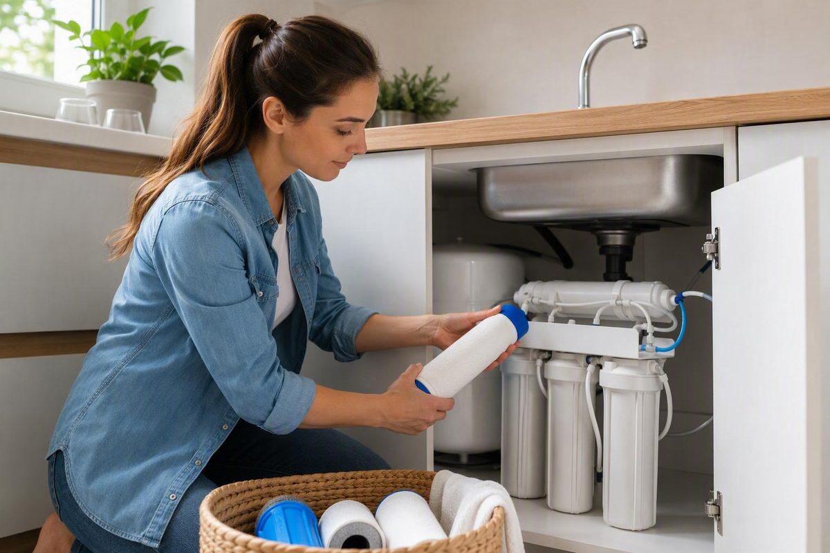
Changing reverse-osmosis filters is usually manageable once you know exactly which system you have. Problems begin when a generic procedure is applied to the wrong hardware: a twist-lock cartridge is treated like a screw-on sump, an inline post-filter is reversed, or a long-life membrane is replaced with the routine prefilters.
The safest approach is model-aware. Identify and document the system first, isolate and depressurize it, service one stage at a time, restore water slowly, follow the manufacturer’s flushing instructions, and inspect again after full pressure returns.
This guide covers the shared steps used on many residential systems. Your system manual controls model-specific details such as cartridge orientation, sanitation, tightening, membrane handling, filter-life resets, and flushing.
Identify the system and every filter before taking it apart
Start with the model number, not with a replacement cartridge that merely appears to fit.
Look for a label on the RO frame, manifold, membrane housing, tank, or cabinet wall. Record:
- Manufacturer and complete model number
- System serial number, if present
- Existing cartridge labels and part numbers
- Cartridge length and diameter
- Housing or module labels
- Stage numbers and stated functions
- Tubing colors, connection points, and flow arrows
- Replacement-set or membrane part numbers listed in the manual
Do not buy filters solely because their dimensions and appearance match. Before substituting a non-OEM cartridge, compare its media, capacity, dimensions, intended stage, and other specifications with the system manufacturer’s requirements. Ask the manufacturer whether the alternative is suitable and whether it changes any applicable certification or warranty terms.
A conventional residential system often sends water through a sediment prefilter, one or more carbon prefilters, an RO membrane, and a final post-filter. One system’s “stage 4” may be its membrane, while another may combine several functions inside one enclosed module. A representative homeowner guide describes the usual sediment, carbon, membrane, and post-filter arrangement, but your manual should determine the actual order for your system and its particular configuration.
Common hardware formats include:
-
Screw-on sumps: Replaceable drop-in cartridges sit inside bowl-shaped housings threaded onto caps.
-
Inline filters: A sealed cylindrical filter connects directly to tubing, often through quick-connect fittings.
- Separate membrane housings: The membrane element sits inside a horizontal or vertical pressure vessel with a removable cap.
- Tankless modules: Enclosed filters insert into an electronic manifold and may be monitored by filter-life indicators.
Before disconnecting either one, check its label, part number, cap design, tubing route, and any flow-direction arrow. If the identity or direction remains uncertain, stop rather than guess.
Before disassembly, take several clear photographs:
- A wide view of the entire system
- A close-up of every stage label
- The housing or cartridge order from left to right
- Every tubing route and fitting
- Flow-direction arrows on inline components
- Cartridge orientation
- Feed, tank, and bypass-valve positions
These photographs are more reliable than trying to remember how several similar white components were arranged.
| Stage function | Common physical format | Typical starting interval | Details to verify for your model |
|---|---|---|---|
| Sediment prefilter | Drop-in cartridge, twist-lock module, or combined tankless filter | 6–12 months | Micron rating, dimensions, stage position, capacity |
| Carbon prefilter | Carbon block, granular-carbon cartridge, or combined module | 6–12 months | Carbon type, source-water requirements, stage order |
| RO membrane | Element inside a separate housing or enclosed membrane module | Roughly 2–5 years | Part number, orientation, seals, performance criteria, startup procedure |
| Carbon post-filter | Inline filter, drop-in cartridge, or twist-lock module | Around 12 months | Flow direction, fitting type, tubing route, capacity |
| Remineralization stage | Inline mineral cartridge or enclosed module | Model-specific | Flow direction, media, flushing procedure |
| UV component | Lamp and sleeve inside a powered chamber | Model-specific | Lamp, sleeve, electrical isolation, restart procedure |
The intervals in the chart are starting ranges, not promises. Vendor maintenance guidance commonly lists prefilters at 6–12 months and membranes at approximately 2–5 years, while noting that water quality and use can change the schedule for a particular installation.
Use the calendar as a starting point, not a universal rule
A replacement date is a maintenance trigger, not a universal expiration date.
As a practical starting point, sediment and carbon prefilters commonly fall in the 6–12-month range, post-filters are often changed at about 12 months, and many residential membranes operate for roughly 2–5 years. These are recurring ranges in vendor maintenance guidance, not fixed standards for every system.
Cartridge size, media capacity, system design, source water, pressure, and household demand all influence service life. The manual’s schedule and performance criteria should therefore take priority.
An instruction to replace “the filters annually” may refer only to a scheduled cartridge set. It does not necessarily mean that the membrane belongs in that set. For example, APEC says that the bottom three filters in the five-stage system covered by its tutorial typically require annual replacement, while its two upper filters may last three to five years under that configuration’s instructions. That is model-specific guidance, not a schedule for every five-stage system.
Conditions that may justify earlier inspection or replacement include:
- High household water consumption
- Heavy sediment loading
- Iron in the source water
- Hard water or scaling conditions
- Chlorine or chloramine exposure
- High feed-water TDS
- Low feed pressure
- A sudden source-water change
- Small cartridges or limited rated capacity
Changes in flow, taste, odor, appearance, visible prefilter discoloration, or TDS can indicate that the system needs attention. They do not identify the failed component by themselves.
For example, reduced flow may result from an old sediment cartridge, a tank that is still refilling, a closed valve, a kinked tube, low feed pressure, or an improperly seated replacement. Rising product-water TDS may indicate a membrane problem, but it can also reflect changed source water or inconsistent sampling conditions.
Inspect or replace scheduled prefilters before concluding that the more expensive membrane has failed. Prefilters are upstream of the membrane and are generally serviced more frequently.
Keep a maintenance log containing:
- Installation date for each cartridge
- Manufacturer and part number
- Source-water observations
- Unusual sediment, iron, taste, or odor
- Changes in faucet flow
- Feed-water TDS
- RO product-water TDS
- Calculated membrane rejection
- Leaks or damaged components found
- Flushing procedure completed
- Date of the delayed leak inspection
A log turns future maintenance into a comparison with the system’s own history rather than a guess based on a generic calendar.
Gather the right supplies and make the work area safe
Have everything within reach before closing a valve or opening a housing.
Basic supply checklist
- Confirmed compatible replacement cartridges
- Correctly sized housing wrench, if required
- Bucket or shallow pan
- Absorbent towels
- Optional clean gloves
- Replacement O-rings specified for the system
- Manufacturer-approved food-grade O-ring lubricant
- Owner’s manual or manufacturer instructions
- Manufacturer support information
- Maintenance log and pen
- Flashlight for inspecting seals and fittings
Clear the cabinet so you can support the housings without twisting the frame. Remove paper goods, cleaning products, and stored items that could be damaged by water. Even after the feed is closed, sumps and tubing retain water.
For many tank-equipped under-sink systems, the basic shutdown sequence is:
- Close the feed-water valve supplying the RO system.
- Close the valve on top of the storage tank.
- Open the RO faucet.
- Wait until flow and pressure subside.
- Position the bucket and towels beneath the assembly.
Valve designs vary. Some use a quarter-turn handle, while others use a knob or a direction marked on the valve body. Confirm that you are operating the correct valve, and do not force an unfamiliar or corroded control.
Use a pressure-relief button only if the system has one and its manual directs you to use it. Do not assume that an unidentified button or fitting on top of a housing is a pressure control.
Warning: Never attempt to unscrew, disconnect, or unlock a pressurized filter housing. If water continues flowing strongly from the faucet or you cannot confirm that the feed is isolated, stop and identify the valve problem before proceeding. Shutdown, faucet depressurization, and electrical-hazard checks are also central precautions in published RO leak guidance before troubleshooting wet equipment.
Water near electricity creates a separate stop condition. If a spill reaches an outlet, pump, UV unit, disposer connection, dishwasher wiring, or other powered equipment, do not reach into the wet area. Disconnect power safely from a dry location before proceeding. If that cannot be done safely, stop and call qualified help.
Keep the manual available throughout the job. It is more useful when confirming cartridge orientation or a restart sequence than after a fitting has already been disconnected incorrectly.
The core replacement workflow for housing-style cartridges
The following workflow applies to systems with drop-in cartridges inside conventional screw-on sumps. It does not automatically apply to twist-lock, inline, membrane, or tankless components.
Published housing-style procedures generally follow the same broad sequence—shut down and depressurize, remove the housing, inspect and replace the cartridge, reassemble without overtightening, restore water, and check for leaks—but system-specific instructions still control the exact method.
-
Verify isolation and depressurization. Confirm that the feed and tank valves are closed as applicable. Leave the RO faucet open until flow has subsided.
-
Place the bucket. Position it directly beneath the first housing. Keep towels around the base of the system.
-
Support the assembly. Hold the manifold or housing as appropriate so loosening force is not transferred entirely to a wall bracket, tubing connection, or neighboring sump.
-
Loosen one housing. Fit the correct housing wrench squarely around the sump and apply steady, even pressure. Keep track of the stage position.
-
Handle a stuck sump cautiously. Recheck that the system is depressurized, then use the correctly sized wrench. Do not strike the housing, add a long extension for extreme leverage, or twist hard enough to bend the bracket. If steady force does not release it, stop before damaging the cap or sump.
-
Lower the housing carefully. It may be nearly full of water. Keep it upright until it is over the bucket.
-
Remove the old cartridge. Lift it out without pouring accumulated sediment into another housing or over the manifold. Follow applicable local disposal requirements and any manufacturer instructions for the used cartridge.
-
Clean the empty housing if permitted. Mild dish soap and warm water may be suitable for routine cleaning when allowed by the manufacturer. Rinse thoroughly so no soap remains. This is physical cleaning, not chemical sanitization. Do not introduce bleach, peroxide, or another sanitizer unless the manufacturer specifies the product, concentration, contact time, rinsing, and restart procedure.
-
Inspect the sump and cap. Use a flashlight to check for damaged threads, deformation, abrasion, and hairline cracks. Replace a cracked pressure-bearing component rather than attempting to compensate with additional tightening.
-
Inspect the O-ring. Depending on the design, remove it gently or inspect it in place. Look for cracks, nicks, brittleness, flat spots, stretching, swelling, or twisting. Replace a damaged or deformed seal with the specified part.
-
Clean the O-ring groove. Remove grit, old lubricant, and sediment without scratching the sealing surface.
-
Seat the seal evenly. The O-ring should lie flat in its intended groove, not on the threads or across an edge. If the manufacturer permits lubrication, apply only a thin film of the approved food-grade silicone product. Lubricant may help a serviceable seal seat, but it cannot repair a cut or flattened O-ring. These inspection, groove-cleaning, and light-lubrication steps are also set out in a vendor’s detailed housing-maintenance guidance for compatible designs.
-
Install the correct cartridge. Use your photographs and stage labels. Sediment commonly comes before carbon, but follow the documented order for the model. Center the cartridge over any locating boss or seat.
-
Thread the sump on by hand. Keep the cartridge centered so it is not pinched between the sump and cap. If the threads resist immediately, back off and start again rather than forcing them.
-
Tighten only as specified. Reassemble the housing snugly without overtightening. Exact wrench use and final tightening methods vary by design. Excessive force can damage the housing, distort a seal, or make the next service difficult.
-
Repeat one stage at a time. Finish and verify one housing before opening the next. This prevents cartridges, O-rings, and sumps from being accidentally interchanged.
Before moving on, compare the completed row of housings with the original photograph. Check stage order, cartridge centering, O-ring position, and thread engagement.
Adapt the procedure to twist-lock, inline, membrane, and tankless filters
Choose the procedure by hardware type:
- Screw-on sump: Use the housing workflow above.
- Twist-lock cartridge: Follow the prescribed release and locking rotation.
- Inline filter: Document tubing and flow direction before disconnection.
- Membrane element: Use separate membrane-service instructions.
- Tankless module: Follow the electronic system’s replacement, reset, and flushing sequence.
- UV or powered stage: Isolate electrical power as instructed and treat it as separate equipment.
Twist-lock cartridges
A twist-lock cartridge may release with a quarter-turn or half-turn, but the direction and amount of rotation are model-specific. Some systems use colors or manifold labels to match cartridges to positions.
Do not remove every similar-looking cylinder automatically. One half-turn system’s procedure expressly tells owners not to remove the center membrane while changing its color-coded filters. It also instructs users to prefill those particular cartridges with tap water as part of that system’s procedure. Neither instruction should be generalized. Prefill a cartridge only when your manufacturer expressly directs it.
Inline filters
Before disconnecting an inline filter:
- Photograph both tube connections.
- Mark the inlet and outlet tubing if needed.
- Locate the flow-direction arrow.
- Record the original orientation and tubing route.
- Confirm the quick-connect release procedure in the manual.
Do not pull tubing from a quick-connect fitting without depressurizing the system and following the fitting instructions. When installing the replacement, align the arrow with the documented direction of flow and ensure that each tube is fully seated.
RO membranes
The membrane normally has a separate, longer service cycle. Do not replace it merely because the sediment and carbon cartridges are due.
Orientation matters. Use the manufacturer’s membrane procedure for removal, seal replacement, sanitation, reassembly, and flushing. If the vessel is inaccessible or the tubing arrangement is unfamiliar, contact the manufacturer or a qualified technician.
Tankless systems
Tankless RO systems often use enclosed modules rather than open sumps. The electronics may not recognize a new filter until the corresponding life indicator is reset. A timed flush may also be required. Vendor instructions for these systems show that reset buttons and flush durations can be module- and model-specific rather than universal.
Do not reset every indicator or copy a button-hold duration from another system.
Alkaline and UV stages
A UV lamp is not an ordinary RO cartridge.
Stop and check the manual or contact support if you encounter:
- Unlabelled or unfamiliar tubing
- A membrane vessel that does not match the diagram
- Damaged quick-connect fittings
- Tubing that will not release or reseat
- A UV lamp, pump, controller, or exposed wiring
- A module that will not unlock with normal hand force
- Missing labels or uncertain flow direction
- A component layout that differs from the manual
Restart slowly, flush correctly, and check twice for leaks
Before restoring water, perform a deliberate pre-start inspection:
- Every sump is correctly threaded and secure.
- Every twist-lock cartridge is fully locked.
- Inline-filter arrows face the documented direction.
- Disturbed tubing is fully seated.
- O-rings remain in their grooves.
- The faucet, tank, feed, and bypass valves are in the expected starting positions.
- Electrical connections are dry and configured as instructed.
- No wrench, towel, packaging, or loose part remains beneath the assembly.
Restore the feed supply slowly. Reopen the storage-tank valve when applicable and in the sequence specified for the model.
Watch:
- Sump-to-cap seams
- Membrane-housing caps
- Twist-lock cartridge interfaces
- Inline-filter connections
- Quick-connect fittings
- Tank valve and tank tubing
- Every connection touched during service
Spilled water can mimic a leak. Dry the housings and fittings completely, then watch for a new droplet. Trace wetness upward to the highest point that becomes wet because water may travel down tubing or along the outside of a sump before dripping.
If a leak appears:
- Close the feed-water valve.
- Close the tank valve when applicable.
- Open the RO faucet to depressurize.
- Dry the area.
- Correct the seal, cartridge, tubing, or component problem.
- Restart slowly and inspect again.
Never attempt to stop an active pressurized leak by applying more wrench force.
Flushing is required, but there is no universal duration or number of discarded tanks. Instructions differ by cartridge media and system design. For example, one twist-in system calls for filling and completely emptying its tank two to three times under its model-oriented procedure. Other systems specify a faucet flush or a different number of tank cycles, so follow the instructions supplied with your model and replacement set.
Compare those effects with the manufacturer’s stated startup behavior. If cloudiness, particles, odor, or unusual taste persists beyond the specified flush, stop using the water and investigate the installation or contact the manufacturer.
For a tank-equipped system, inspect twice:
- Immediate check: While feed pressure first returns
- Delayed check: After the storage tank has refilled and the system has returned to normal operating pressure
Published vendor guidance specifically recommends monitoring the system over the following days because leaks may emerge after pressure builds and the system cycles. Recheck the cabinet after several fill-and-draw cycles.
Evaluate the membrane with trends, not one magic TDS number
Routine prefilter service and membrane evaluation are separate tasks. A membrane should not automatically be replaced whenever the sediment or carbon cartridges are changed.
A handheld TDS meter can help track broad changes in dissolved-ion concentration. For a useful comparison, take feed-water and RO product-water readings under reasonably similar conditions:
-
Complete the manufacturer-required flush.
-
Record the feed-water TDS.
- Record the RO product-water TDS.
- Calculate rejection.
The formula is:
Rejection (\%) = Feed TDS - RO TDS ÷ Feed TDS × 100
Illustration only: If feed water measures 300 ppm and RO product water measures 30 ppm:
300-30 ÷ 300 × 100 = 90\%
The arithmetic gives a 90% calculated rejection for those two readings. It is not a universal pass-fail standard. The rejection formula and the need to compare performance trends rather than rely on one reading are described in detailed RO maintenance guidance for homeowners.
Compare the result with:
- The system’s readings when the membrane was performing normally
- The membrane manufacturer’s criteria
- Current feed-water TDS
- Previous readings taken under similar tank and operating conditions
A single result can mislead if source-water TDS changed, the system was recently flushed, the tank was at a different point in its cycle, or the meter and sampling technique differed.
TDS is a broad performance indicator. It does not identify individual dissolved substances, detect every possible contaminant, or establish that water is safe to drink. A normal-looking TDS result cannot substitute for appropriate contaminant testing.
Treat these as prompts for diagnosis rather than proof of membrane failure:
- Rising product-water TDS
- Declining calculated rejection
- Reduced production or faucet flow
- Taste or odor changes
Before condemning the membrane, check:
- Prefilter age
- Feed and tank valve positions
- Cartridge order and seating
- Feed pressure
- Kinked or disturbed tubing
- Storage-tank behavior
- Flow-restrictor condition
- Recent source-water changes
- Model-specific bypass or control settings
If membrane service is justified, follow the manufacturer’s documented procedure for removal, housing sanitation, seals, orientation, startup, and flushing.
Troubleshoot common post-change problems and know when to stop
Always isolate the feed, close the tank when applicable, and depressurize the system before opening a housing or disconnecting a fitting.
| Symptom | Likely causes | Safe checks | Stop conditions |
|---|---|---|---|
| Housing leaks at the cap | Twisted, missing, displaced, or damaged O-ring; dirty groove; off-center cartridge; cross-threading; cracked sump | Shut down, depressurize, inspect and clean the sealing surfaces, center the cartridge, and reassemble as specified | Cracked housing, damaged threads, recurring leak |
| Fitting or tubing leaks | Tube not fully seated, angled or damaged tube end, damaged fitting, incorrect reassembly | Dry the area, identify the highest wet point, and follow the fitting maker’s inspection procedure | Cracked connector or tubing that cannot be removed or reseated correctly |
| System does not restart | Feed or tank valve closed, cartridge not locked, disturbed connection, electronic control not reset | Confirm valve positions, cartridge engagement, tubing, power, and the model-specific reset | Persistent failure, pump fault, or controller error |
| Low faucet flow | Tank still refilling, trapped air, low feed or tank pressure, kinked tubing, incorrect seating, blocked restrictor | Allow the specified refill time and inspect valve positions, tubing routes, and cartridge seating | Damaged tank, unresolved pressure issue, unfamiliar restrictor work |
| Cloudy water | Trapped air or incomplete startup flush | Compare with the manual’s expected startup behavior and complete only the specified flush | Cloudiness persists beyond the documented flush |
| Dark particles | Carbon fines from a new filter or incorrect cartridge handling | Follow the prescribed flush and verify cartridge identity | Particles persist or the cartridge appears damaged |
| Unusual taste or odor | Incomplete flush, reversed inline filter, incorrect cartridge, stagnant tank, source-water change | Verify stage order, flow arrows, part numbers, and the flushing record | Persistent or worsening condition |
| Higher product-water TDS | Different testing conditions, incomplete flushing, overdue prefilters, membrane deterioration, installation error | Repeat comparable feed and product readings and compare rejection trends | Unresolved decline or manufacturer criteria indicate service |
| Filter-life warning remains on | Wrong indicator reset, module not recognized, reset not completed | Follow the exact reset procedure for the replaced module | Controller error or filter not recognized |
| Leak appears later | Joint or seal leaks after pressure returns | Shut down, depressurize, dry, and inspect the affected joint | Persistent leakage or a damaged pressure-bearing part |
For a leaking housing, do not assume it simply needs more torque. Check for a displaced or damaged O-ring, dirty groove, off-center cartridge, thread damage, or hairline crack. Overtightening does not repair a failed seal and may damage the housing. Leak guidance for RO systems likewise calls for depressurization, O-ring inspection, tracing water to its highest wet point, and replacement of cracked pressure-bearing parts rather than additional tightening.
For quick-connect tubing, verify that the tube end is clean, square, and fully seated. Follow the fitting manufacturer’s procedure before releasing, trimming, or reinserting it. Do not improvise with sealants on a connection that was not designed for them.
Stop and contact the manufacturer or a qualified technician for:
- A leak that returns after correct depressurization and reseating
- A cracked housing or manifold
- A damaged, corroded, or leaking storage tank
- Unfamiliar membrane or tubing work
- A failed quick-connect fitting
- UV equipment or powered components you cannot isolate safely
- Water near an outlet or appliance wiring
- Unresolved loss of flow or worsening performance
- A configuration that does not match the manual
Printable final checklist
- [ ] System model and serial number recorded
- [ ] Replacement part numbers recorded
- [ ] Before-disassembly photographs saved
- [ ] Feed water isolated
- [ ] Storage-tank valve closed when applicable
- [ ] Faucet opened and pressure relieved
- [ ] Cartridges installed in the correct stages
- [ ] Flow arrows and cartridge orientation verified
- [ ] O-rings inspected and seated
- [ ] Housings reassembled without overtightening
- [ ] Disturbed tubing fully seated
- [ ] Feed and tank valves reopened as directed
- [ ] Required electronic indicator reset
- [ ] Manufacturer-specified flush completed
- [ ] Immediate leak check completed
- [ ] Delayed full-pressure leak check scheduled
- [ ] Replacement date entered in the maintenance log
- [ ] Baseline flow and TDS readings recorded
Frequently asked questions
Do I need to replace the RO membrane every time I change the prefilters?
No. Sediment and carbon prefilters are normally changed more often than the RO membrane. Typical vendor guidance places prefilters in the 6–12-month range and many membranes at roughly 2–5 years, although the correct schedule depends on the system, source water, household use, and manufacturer’s criteria for that model.
Evaluate the membrane separately using its service history, product-water TDS trend, calculated rejection, flow, and model-specific guidance. Check overdue prefilters, valve positions, tubing, and cartridge installation before deciding that the membrane has failed.
How many tankfuls should I discard after changing reverse-osmosis filters?
Use the number specified by the system or cartridge manufacturer. There is no universal answer.
Published model-specific procedures differ. One twist-in system specifies two to three complete fill-and-drain cycles after replacement for its equipment, while other systems use different flushing sequences. Do not shorten the required flush because the water looks clear, and do not assume that extra flushing can correct an installation error.
Why is my reverse-osmosis filter housing leaking after replacement?
Shut off the feed, close the tank if applicable, and open the faucet to depressurize before touching the housing. Dry everything, locate the highest point that becomes wet, and inspect the seal and pressure-bearing parts. Replace damaged seals or housings. Do not try to repair a leak by tightening a pressurized sump.
Can a TDS meter tell me when the RO membrane needs replacement?
It can help, but it cannot make the decision by itself. Record comparable feed-water and RO-water TDS readings, calculate rejection, and compare the trend with the system’s earlier baseline and manufacturer criteria.
TDS does not identify individual contaminants and does not prove that the water is safe. A changed result may also reflect source-water variation, tank status, recent flushing, or inconsistent testing technique. Diagnose those variables and check the prefilters before replacing the membrane.
Can I change reverse-osmosis filters myself, or should I call a professional?
Many homeowners can replace conventional sediment and carbon cartridges when the system is clearly identified, accessible, depressurized, and covered by understandable manufacturer instructions.
The job becomes less suitable for DIY work when it involves unfamiliar membrane plumbing, damaged fittings, inaccessible components, a corroded tank, persistent leaks, UV equipment, pumps, controllers, or water near electricity.
Whether you do the work yourself or call for help, follow the same essentials: use confirmed parts, preserve stage order, depressurize before opening anything, avoid excessive force, restore water slowly, complete the specified flush, and inspect again after full pressure returns.
Changing reverse-osmosis filters successfully comes down to a controlled sequence: verify the model and parts, document the stage order, isolate and depressurize the system, service each cartridge and seal carefully, restore water slowly, flush exactly as directed, and inspect again after pressure builds.
Replacement calendars and TDS readings are useful maintenance tools, but neither is a universal rule or a water-safety test. Save the completed maintenance log. If the membrane, tubing, electrical equipment, or symptoms do not match the documented procedure, contact the manufacturer or qualified help instead of improvising.